


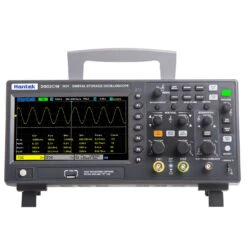


Hantek DSO2C10 Digital Oscilloscope 2CH Digital Storage 1GS/s Sampling Rate 100MHz Bandwidth Dual Channel Economical Oscilloscope
Original price was: $192.30.$96.99Current price is: $96.99.
- Safeguard Your Shopping Experience
- Online assistance, always at your service.
- Buy with confidence, backed by quality.
- There are quality problems, free return and exchange

Features:
1), 2 channels, each channel has independent knob control;
2), Analog bandwidth 100MHZ
3) The highest sampling rate is 1 GSa/s;
4), The storage depth is 8Mpts;
5), The vertical range of 2mV/div ~ 10V/div;
6) Vertical resolution: 8bit;
7) Trigger: edge, pulse, video, slope, timeout, window, pattern, interval, runt, UART, LIN, CAN, SPI, IIC;
8) Bus decoding and protocol analysis: RS232/UART, I2C, SPI, CAN, LIN;
9), Can save settings, waveforms, reference waveforms, CSV, pictures and other data formats.
10), 3-digit digital voltmeter and 6-digit frequency meter functions;
11) Support 32 kinds of automatic measurement and statistics functions, real-time statistics of minimum, maximum, standard deviation and other statistical information;
12), Two groups of digital voltmeter functions;
13) Support threshold test to realize free measurement in the screen;
14), Rich SCPI remote control instructions;
15). Provide multiple types of peripheral interfaces: USB Host/Device.
Product Model(NOTE:Click on the model to reach the purchase link of the corresponding model):
| Model |
Channels |
Bandwidth |
Sampling Rate |
Storage Depth |
Signal Source (AWG) |
|
|
2CH |
100MHz |
1GSa/S | 8M | / |
|
|
2CH | 150MHz | 1GSa/S |
8M |
/ |
|
|
2CH+1CH | 100MHz | 1GSa/S |
8M |
1CH |
|
|
2CH+1CH |
150MHz | 1GSa/S |
8M |
1CH |
Specification:
| model | DSO2C10 | |||
| bandwidth | 150MHz | 100MHz | 150MHz | 100MHz |
| Number of oscilloscope channels | 2CH | 2CH | 2CH | 2CH |
| Built-in signal source | 1CH | 1CH | – | – |
| Oscilloscope index | ||||
| Sampling rate range | 1GSa/s (single channel), 500MSa/s (dual channel) | |||
| Collection method | ||||
| sampling | Sample data | |||
| Peak-to-peak | Display high frequency and random glitches | |||
| average value | Average waveform, times: 4, 8, 16, 32, 64, 128 | |||
| High precision | Up to 12bit | |||
| enter | ||||
| Input coupling | DC, AC or ground (DC, AC, GND) | |||
| input resistance | 1MΩ±2% ‖20pF±3pF | |||
| Probe attenuation coefficient setting | 1X, 10X, 100X, 1000X | |||
| Voltage level | 300V CAT II | |||
| Maximum input voltage | 300VRMS (10X) | |||
| Horizontal system | ||||
| Waveform interpolation | (sin x)/x | |||
| Maximum record length | Maximum 8M per channel | |||
| Maximum 4M for dual channels | ||||
| Horizontal scale range | 2ns/div~100s/div 1, 2, 5 steps | |||
| Time base mode | YT, XY, Roll | |||
| Zero offsets | ±0.5 div×minimum time base gear | |||
| Sampling rate and delay time accuracy | ±50ppm | |||
| Clock drift | ≤±5 ppm/year | |||
| Incremental time measurement accuracy | Single, “sampled” mode | |||
| (Full bandwidth) | ±(1 sampling interval+100ppm×reading+0.6ns) | |||
| >16 times above average | ||||
| ±(1 sampling interval+100ppm×reading+0.4ns) | ||||
| Sampling interval = second/div÷200 | ||||
| Vertical system | ||||
| model | DSO2D15 | DSO2D10 | DSO2C15 | DSO2C10 |
| bandwidth | 150MHz | 100MHz | 150MHz | 100MHz |
| Rise time at BNC (typical) | 2.3ns | 3.5ns | 2.3ns | 3.5ns |
| Vertical resolution | 8-bit resolution, simultaneous sampling for each channel | |||
| Vertical sensitivity | 2mV/div to 10V/div | |||
| Offsets range | 2mV/div to 20mV/div, ±100mV; 50mV/div to 200mV/div, ±1V; | |||
| 500mV / div to 2V / cell, ± 10V; 5V / div to 10V / division, ± 50V | ||||
| computation | Add, subtract, multiply, divide, FFT | |||
| FFT | Window: Rectangular, Hanning, Hamming, Brackman, Bartlett, flat top window | |||
| Bandwidth limit | 20MHz | |||
| Low frequency response (-3db) | ≤10Hz at BNC | |||
| Vertical gain accuracy | In the “sample” or “average” acquisition mode, the accuracy of 10V/div to 10mV/div is ±3%; | |||
| In “Sampling” or “Average” acquisition mode, the accuracy of 5mV/div to 2mV/div is ±4% | ||||
| DC offsets accuracy | ±0.1 div±2 mV±1% offsets value | |||
| Voltage measurement repeatability, average acquisition mode | Under the same settings and environmental conditions, the voltage increment between any two sets of average values of more than 16 waveforms: ±(3%×reading+0.05 division) | |||
| Note: The bandwidth is reduced to 6MHz when using X1 probe | ||||
| Trigger system | ||||
| Trigger type | Edge, pulse, video, slope, timeout, window, pattern, interval, runt, UART, LIN, CAN, SPI, IIC | |||
| Trigger level range | ±5 divisions from the center of the screen | |||
| Trigger mode | Automatic, normal, single | |||
| Level | CH1~CH2 | ±4 divisions from the center of the display | ||
| EXT | 0~3.3V | |||
| Range of relief | 8ns~10s | |||
| Trigger level accuracy | CH1~CH2 | 0.2 divisions × volts/div within ±4 divisions from the center display | ||
| EXT | ±(6%+40mV of setting value) | |||
| Edge Trigger | Slope | Rising edge, falling edge, rising edge or falling edge | ||
| Source | CH1, CH2, EXT | |||
| Pulse width trigger | polarity | Positive polarity, negative polarity | ||
| Condition (When) | <, >, !=, = | |||
| Source | CH1~CH2, | |||
| Pulse width range | 8ns ~ 10s | |||
| Precision | 8ns | |||
| Video trigger | Signal standard | NTSC, PAL | ||
| Source | CH1~CH2 | |||
| Synchronize | Scan line, line number, odd field, even field, all field | |||
| Slope trigger | Slope | Rise and fall | ||
| Condition (When) | <,>, !=, = | |||
| Source | CH1 ~ CH2 | |||
| time limit | 8ns ~ 10s | |||
| Precision | 8ns | |||
| Timeout trigger | Source | CH1~CH2, | ||
| polarity | Positive polarity, negative polarity | |||
| time limit | 8ns ~ 10s | |||
| Precision | 8ns | |||
| Window trigger | Source | CH1~CH2 | ||
| Pattern trigger | Pattern | 0: low level; 1: high level; X: ignore; :rising; :falling; :rising or falling | ||
| Level (source) | CH1~CH2 | |||
| Interval trigger | Slope | Rise and fall | ||
| Condition (When) | <,>, !=, = | |||
| Source | CH1~CH2, | |||
| time limit | 8ns ~ 10s | |||
| Precision | 8ns | |||
| Runt trigger | polarity | Positive polarity, negative polarity | ||
| Condition (When) | <,>, !=, = | |||
| Source | CH1~CH2 | |||
| time limit | 8ns ~ 10s | |||
| Precision | 8ns | |||
| UART trigger | Condition (When) | Start, stop, data, parity, receive error | ||
| Source (RX/TX) | CH1~CH2 | |||
| Data Format | Hex (hexadecimal) | |||
| Data length | 1 byte | |||
| Data bit width | 5 bit, 6 bit, 7 bit, 8 bit | |||
| Parity check | None, odd, even | |||
| Idle level | High, low | |||
| Baud rate (optional) | 110/300/600/1200/2400/4800/9600/14400/19200/38400/57600/115200/230400/380400/460400 bit/s | |||
| Baud rate (custom) | 300bit/s~334000bit/s | |||
| LIN trigger | Condition (When) | Interval field, sync field, ID field, sync error, identifier, ID and data | ||
| Source | CH1~CH2, | |||
| Data Format | Hex (hexadecimal) | |||
| Baud rate (optional) | 110/300/600/1200/2400/4800/9600/14400/19200/38400/57600/115200/230400/380400/460400 bit/s | |||
| Baud rate (custom) | 300bit/s~334000bit/s | |||
| CAN trigger | Condition (When) | Start bit, remote frame ID, data frame ID, frame ID, remote frame data, data frame data, error frame, all errors, response error, overload frame | ||
| Source | CH1~CH2 | |||
| Data Format | Hex (hexadecimal) | |||
| Baud rate (optional) | 10000, 20000, 33300, 500000, 62500, 83300, 100000, 125000, 250000, 500000, 800000, 1000000 | |||
| Baud rate (custom) | 5kbit/s~1Mbit/s | |||
| SPI trigger | Source | CH1~CH2, | ||
| Data Format | Hex (hexadecimal) | |||
| Data bit width | 4, 8, 16, 24, 32 | |||
| IIC trigger | Source (SDA/SCL) | CH1~CH2, | ||
| Data Format | Hex (hexadecimal) | |||
| Data index | 0~7 | |||
| Timing (condition) | Start bits, stop bits, no answer, address, data, reboot | |||
| measuring | ||||
| cursor | Voltage difference between cursors△V | |||
| Time difference between cursors△T | ||||
| The reciprocal of △T, in Hertz (1/△T) | ||||
| Automatic measurement | Frequency, period, average value, peak-to-peak value, root mean square, minimum value, maximum value, rise time, fall time, positive pulse width, negative pulse width, bottom value, top value, middle value, amplitude, overshoot , Preshoot, rising edge phase difference, falling edge phase difference, positive duty cycle, negative duty cycle, cycle average, cycle root mean square, falling edge overshoot, rising edge preshoot, BWIDTH, FRF, FFR, LRR , LRF, LFR, LFF | |||
| DVM | data source | CH1, CH2 | ||
| Measurement type | DC effective value | |||
| AC effective value | ||||
| Direct current | ||||
| frequency meter | Hardware 6-digit frequency counter | |||
| Signal source indicator | ||||
| Number of channels | 1 channel | |||
| Sampling Rate | 200MSa/s | |||
| Vertical resolution | 12 bits | |||
| Highest frequency | 25 MHz | |||
| Standard waveform | Sine, square wave, pulse, triangle wave, sampling wave, exponential wave, noise | |||
| Arbitrary waveform | Arb1, Arb2, Arb3, Arb4 | |||
| Sine | Frequency Range | 0.1Hz~25MHz | ||
| Square wave/pulse | Frequency Range | 0.1Hz ~ 10MHz | ||
| Triangle wave | Frequency Range | 0.1Hz~1MHz | ||
| Sample wave | Frequency Range | 0.1Hz~1MHz | ||
| Exponential wave | Frequency Range | 0.1Hz~5MHz | ||
| noise | ||||
| Arbitrary Wave 1 | Frequency Range | 0.1 Hz to 10 MHz | ||
| Arbitrary Wave 2 | Frequency Range | 0.1 Hz to 10 MHz | ||
| Arbitrary Wave 3 | Frequency Range | 0.1 Hz to 10 MHz | ||
| Arbitrary Wave 4 | Frequency Range | 0.1 Hz to 10 MHz | ||
| Wave length | 8KSa | |||
| frequency | Precision | 100 ppm (less than 10 kHz) 50 ppm (greater than 10 kHz) | ||
| Resolution | 0.1 Hz or 4 bits, whichever is greater | |||
| Amplitude | Output range | 10mV~7Vp-p (high impedance) | ||
| 5mV~3.5Vp-p(50Ω) | ||||
| DC offsets | range | ±3.5 V, high resistance | ||
| ±1.75 V, 50 Ω | ||||
| Resolution | 100 μV or 3 bits, whichever is greater | |||
| Precision | 2% (1 kHz) | |||
| Output impedance | 50 Ω | |||
| General technical specifications | ||||
| display | Display type | 7″ TFT LCD display diagonally | ||
| Display resolution | 800 (horizontal) * 480 (vertical) pixels | |||
| Display color | 16 million colors (24 bit true color) | |||
| Afterglow time | Minimum value, 1 s, 5 s, 10 s, 30S, unlimited | |||
| Display type | Point, vector | |||
| Display brightness | Adjustable | |||
| Grid type | Optional | |||
| Grid brightness | Adjustable | |||
| interface | Standard interface | USB Host, USB Device | ||
| General technical specifications | Probe compensator output | |||
| Output voltage, typical | About 2Vpp input ≥1MΩ load | |||
| Frequency, typical | 1kHz | |||
| voltage | 100-120VAC RMS (±10%), 45Hz to 440Hz, CATⅡ | |||
| 120-240VAC RMS (±10%), 45Hz to 66Hz, CATⅡ | ||||
| Power consumption | Less than 30W | |||
| Fuse | T, 3.15A, 250V, 5x20mm | |||
| Operating temperature | 0~50 °C (32~122 °F) | |||
| storage temperature | -40~+71 °C (-40~159.8 °F) | |||
| humidity | ≤+104℉(≤+40°C): ≤90% relative humidity | |||
| 106℉~122℉ (+41°C ~50°C): ≤60% relative humidity | ||||
| Altitude | When operating and not operating | 3,000m (10,000 feet) | ||
| Mechanical shock | Random vibration | 0.31g RMS from 50Hz to 500Hz , | ||
| 10 minutes per axis | ||||
| When not operating | 2.46g RMS from 5Hz to 500Hz , | |||
| 10 minutes per axis | ||||
| During operation | 50g, 11ms, half sine wave | |||
| Mechanical part | Oscilloscope size | 318 x 140 x 150mm (length x width x height) | ||
| weight |
2900g |
|||
Package includes:
1 X Hantek DSO2C10 Digital Oscilloscope
Details pictures:
Be the first to review “Hantek DSO2C10 Digital Oscilloscope 2CH Digital Storage 1GS/s Sampling Rate 100MHz Bandwidth Dual Channel Economical Oscilloscope”
Related products

Measurement & Analysis Instruments
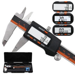
DANIU 150mm Stainless Steel LCD Screen Display Digital Caliper 6 Inch Fraction / MM / Inch High Prec
Digital Multimeters & Oscilloscope
Measurement & Analysis Instruments
Measurement & Analysis Instruments
Digital Multimeters & Oscilloscope
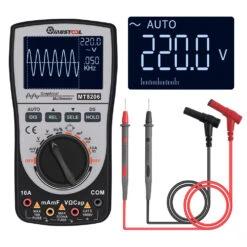
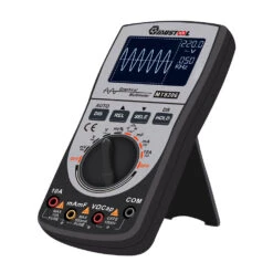
MUSTOOL MT8206 2 In 1 Intelligent Digital Oscilloscope Multimeter With Analog Bar Graph


Digital Multimeters & Oscilloscope
Digital Multimeters & Oscilloscope

Measurement & Analysis Instruments
Reviews
There are no reviews yet.